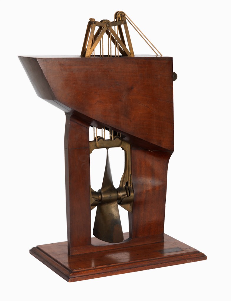
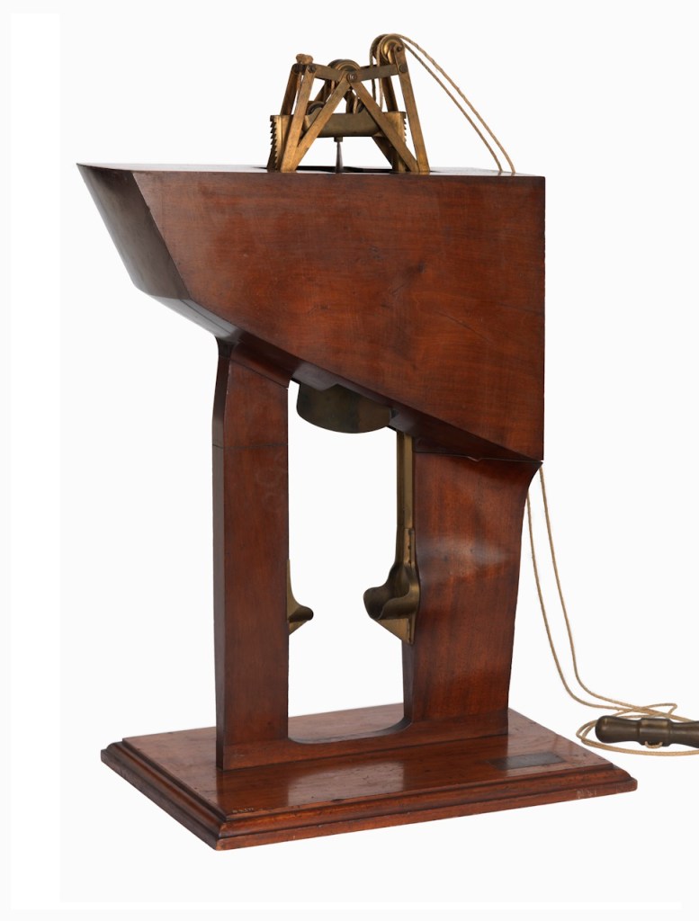
As Improvements in Naval Architecture shows, Lang remained proud of his program of modification of the Franklin ships long after both ships and their crews had vanished. Ships mentioned earlier in this post reappear in the Franklin saga: Rattler assisted in towing both ships towards the Orkneys, while Phoenix would participate in sustaining the search expeditions of the 1850s. An unidentified, undated model in the National Maritime Museum helps illustrate a very similar propeller installation as Lang’s sleek designs for Rattler (upgraded), Phoenix, Intrepid, Pioneer, and other purpose-built steamships. The model has an elaborate mechanism for demonstrating the lifting of the propeller frame, which appears to take the place of the mizzen mast lifting apparatus in real ships (as I have not seen this conspicuous arrangement in any contemporary illustration):
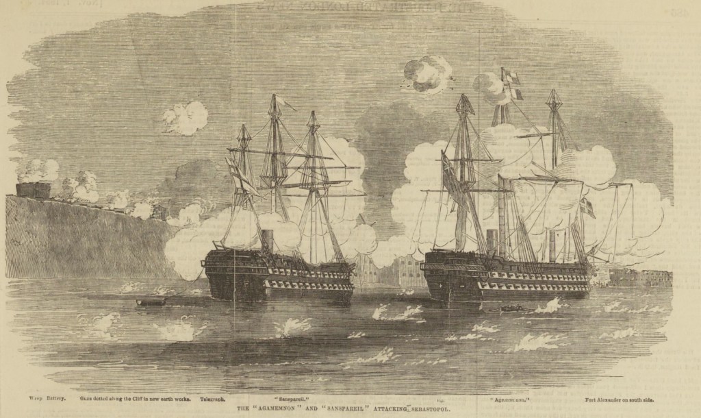
Screw technology was applied to progressively larger warships. After the modification of a handful of guard or block ships to screws, HMS Sans Pareil (1852) was converted on the stocks, to become the first screw-propelled British line of battle ship. Lang was involved in the design of the first purpose-built screw-propelled British battleship, the huge 91-cannon HMS Agamemnon (1853).11
When planning my miniature interpretation of the wreck site in early 2022 – more than five years after the discovery of the Terror – I believed that the propeller was not installed. I thought it could have either been raised into its protective trunk at the stern of Captain Francis Crozier’s cabin, or that it would eventually be located somewhere nearby. A sketch I worked up of the Terror site, made concurrently with the model, illustrated my overall understanding of this area. Over at Wilmot and Crampton Bay, at Erebus’s wreck site, one of these screws lies on the seabed in the debris field.
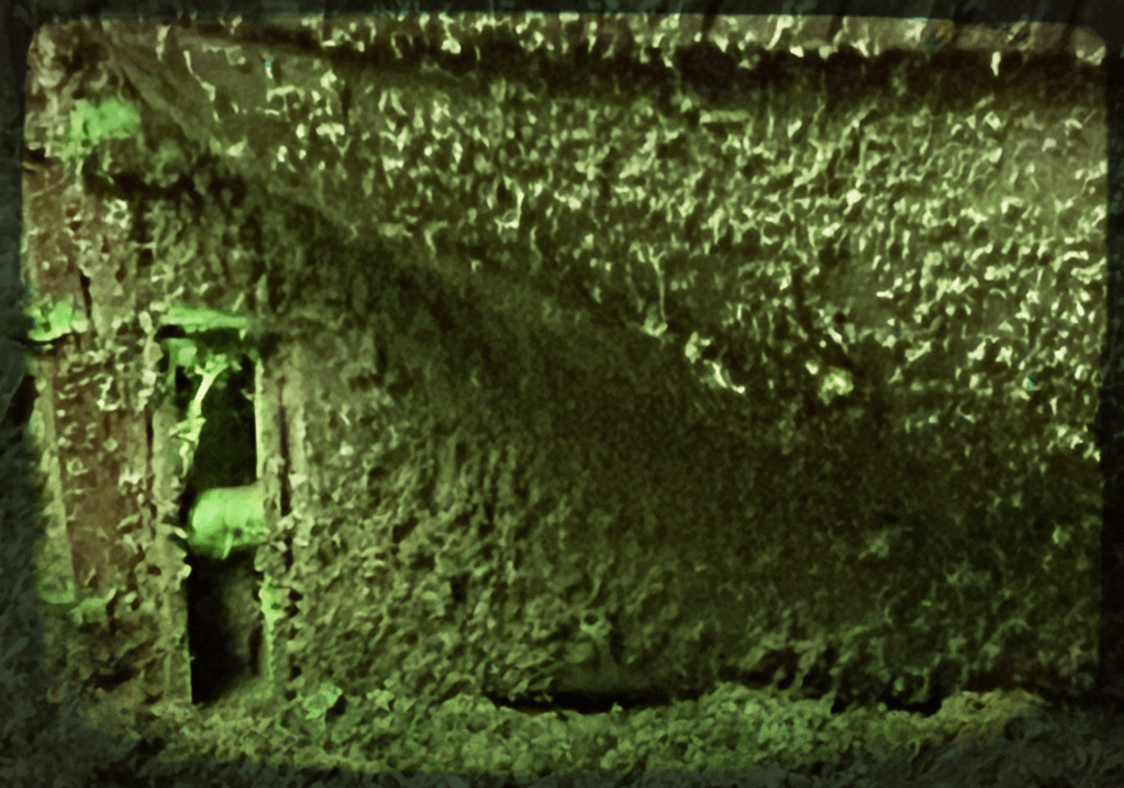
I set to work at the modelling bench scratch-building an aperture and propeller in 1/130 scale. Fortunately, my rebuilding of the Terror model in late 2024 had strengthened the rudder post at the very stern of the ship and added gudgeons (the hardware that a rudder – here absent – normally hangs and pivots from). Terror‘s “deadwood” at the stern could now bear the strain of further alteration! A deeply incised rectangular outline existed for the cavity (after all, I had believed the cavity was closed off by the filling chock). I drilled and carved through the balsa wood to open the aperture up. The screw was scratch built from a cut-down COVID test stick, incised with channels to fit the twin blades, each cut from Evergreen scale models’ .010″ X .250” styrene bent to vary the pitch of the blades as they widened to their outside edges. And voila! The wreck diorama has been updated again to better interpret HMS Terror’s fascinating wreck site.

As usual with any piece of Franklin Expedition information, the position of this propeller at the wreck site raises questions: Was the ship prepared for navigating either by sail or steam? Why is the screw, only intended to be used for short periods, now installed? Was the screw damaged to the extent that it could not be lifted? Why is the rudder not installed on the rudder post just behind the aperture? Does this detail add anything to the overall narrative of the final days of the Expedition? As the Parks Canada archaeological program continues to deliver new information, Franklin scholars and enthusiasts will sail or steam onwards into the seas of speculation to attempt to answer these questions! Leave us a comment with your theories!
I would like to acknowledge the assistance of Jonathan Moore at Parks Canada who has continued to share his expertise, and also reviewed an early version of this post.
References:
- “The Great Terror Wreck Repair [2025]” https://warsearcher.com/2024/12/30/the-great-terror-wreck-repair2024/ ↩︎
- David C. Woodman “Anchors and Propellers” [2025] https://www.aglooka.ca/anchors-and-propellers/ (accessed 2025-03). ↩︎
- Another interesting feature of the photo is it is the only image I have seen of the intersection of the seabed with the shipwreck’s lower hull. Here we see a level seabed, which comes up to the lower lip of the propeller aperture. This area is actually five feet ABOVE the keel and bottom of the stern and rudder posts. ↩︎
- Parks Canada, Nattilik Heritage Society, Franklin Interim Advisory Committee, Wrecks of HMS Erebus and HMS Terror National Historic Site of Canada – Kitikmeot Region (Qitikmiut), Nunavut – Commemorative Integrity Statement (Dec.2019) https://nattilikheritage.ca/wp-content/uploads/2022/10/3.-cis-wet-nhs-final-final_04-dec-2019-copy.pdf P.16 (accessed 2025-03) ↩︎
- John Ross’s small ship Victory was fitted with small, delicate looking removable paddles, which could be rotated to propel the vessel when connected to an experimental high-pressure boiler. ↩︎
- Dr. Matthew Betts HMS Terror – The Design, Fitting and Voyages of the Polar Discovery Ship (Seaforth: 2022) Pages 70-71. For more technical information about this remarkable design, see also pages 92-94. For a larger model representation of this space, see Dr. Betts’ online blog post “HMS Terror’s Screw Propeller” which also provides information on the engineering work on the chock, whose design later applied to other steam screw-propelled vessels : https://buildingterror.blogspot.com/2014/04/hms-terrors-screw-propeller.html (accessed 2025-03). Dr. Betts established that Terror and Erebus’s propellers were not, in fact, frame mounted, like most other of Lang’s designs, but hung independently. ↩︎
- One obvious advantage of screw steamers over paddle-wheelers was that, in an era when the principle warship armament remained cannon disposed along the length of the hull and oriented to fire broadsides of shot at their opponents, arrayed in lines of battle, the paddle wheel machinery interfered with the siting of guns along that broadside. The screw machinery was internal and confined to the after hold, and so, did not interfere with the placement of cannon. ↩︎
- Oliver Lang, Improvement in Naval Architecture Edwards: 1853. (available digitized on Google Books, using British Library’s edition). This whole section of the post follows closely his chronological list of improvements. Page 33 and the second page of his chapter “A Brief list of Services” summarizes his improvements to Erebus and Terror (with the above quote), while the first page notes his original work on the Polar Expedition vessels of 1818, Alexander, Isabella, Trent, Dorothea, and strengthening applied to all subsequent polar vessels. Arguably, what we today call the Parry scheme of polar modification should be called the Parry-Lang scheme! (accessed 2025-03) ↩︎
- A remarkable source of information exists about HMS Phoenix’s 1844-45 modifications and various trials and propellers (of this and other ships mentioned in this post) is located online at pdavis “The Victorian Royal Navy – Vessels – HMS Phoenix” list of Times (of London) references to HMS Phoenix: https://www.pdavis.nl/ShowShip.php?id=200 (accessed 2025-03 – elsewhere cited to William M. Looney) ↩︎
- As quoted in Potter, Koellner, Carney, Williamson, May we be spared to meet on earth : letters of the lost Franklin Arctic expedition (McGill-Queen’s University Press 2022) P.75. ↩︎
- See Lang’s design model for the stern of the Agamemnon (1852) at the National Maritime Museum- SLR2225). Remarkably, France had commissioned Le Napoléon, the first purpose-built steam battleship in the World, before either Agamemnon, the similar James Watt, or even the converted Sans Pareil were complete. There had also been a small number of modified screw-propelled guardships, which were cut-down two-deckers of the Vengeur class. These modifications, starting in 1846 with HMS Blenheim, produced down-rated vessels too small to remain in the traditional line of battle. See a very interesting model (1891-141) in the Science Museum Group’s collection for a look at Blenheim’s screw design. Le Napoléon was designed by Henri Dupuy de Lôme, who had studied steam-powered screw propulsion in England in the early 1840s and would go on to design the first iron-clad warship, Gloire. ↩︎

Thanks for another brilliantly researched post (no pun intended). Regarding the rudder, It’s removal would have been essential whilst overwintering. Must have had quite an effect on morale when it was being removed. In my novel, ‘Passage’, I’ve attempted to recreate the scene from Crozier’s cabin:
He’d been out on deck all morning overseeing the preparation of Terror for overwintering, but now, as he smelled the malt of the whiskey mingle with the steam of his hot, pusser’s tea, he could feel some of the warmth creep back into his body, temporarily easing the knot that was beginning to twist and turn in his stomach. Overhead, he could hear the scuffling of busy sea boots on the quarterdeck above—along with the muffled voices of struggling men as they prepared to take the strain of Terror’s rudder. Crozier listened miserably as it was unhitched from its pintles before the men above began to haul away so that the rudder’s full weight graunched unwillingly up its Woolwich-designed transom channel. The innovation of a detachable rudder had been truly revolutionary but what captain could ever feel entirely comfortable in a rudderless ship? No one understood better than Crozier how sacrifices had to be made everywhere when it came to preparing the ships for overwintering, but as the five-ton timber rumbled its way up towards the deck, he felt nothing but despair in the planned disablement of his ship. To his ears, it was the grating of a tomb being sealed as he tried to ready himself for yet another long, dark winter trapped in the ice.
Thank you for inserting this lyrical passage from your novel! Woolwich indeed! It was so nice to read new life breathed into the Franklin World! Yes, the removal of the massive rudder and many other details are consistent with the vessel closed down and buttoned-up for overwintering. The screw is not, but it could have become damaged or somehow forced or wedged in the aperture.